Currently reading:
Problem with contactors wired in parallel

Discuss Problem with contactors wired in parallel in the Electricians' Talk area at ElectriciansForums.net

hmmmnz

-
Reaction score
26
OK I've got 2 contactors where the coils are wired in parallel.
They are sitting right next to each other,
One pulls in and holds perfectly well. The other pulls in and drops out. Pulls in again drops out. Ect. Ect. For as long as you are trying to keep the contacts closed.

I've tried swapping out contactors, I've tried swapping the wiring around,

Same thing.

This is an established system that's been working fine for probably as long as I've been alive. :D

Any clues on what to try.


Cheers
 
Have you proven that the coils are indeed wired in parallel and that the voltage at the coil terminals is what you expect it to be, correct for the coil and constantly energised?

What is the voltage? AC or DC? What type of contactor? How rapidly does it operate & release?
 
I have seen contactors that were originally 2 no + 2nc
changed for 3no +1nc or 4no etc, you get the idea.
can have some very strange effects on machine opperation
 
maybe the first coil contactor is providing current to a latching contact which brings in the second coil has developed a fault
 
there are so many ways the 2 contactors could interact with each other it can only be speculation or suggestions of what "may be wrong" some more info from the op would be great.
 
The OP does say specifically at the beginning that the coils are wired in parallel, i.e they should both energise and release at the same time regardless of anything else. This then suggests one coil is faulty or the wrong type, but he claims to have substituted them.

I recently had a head-scratcher where I had made a similar assumption that two relay coils were paralleled. They looked like it and tested like it, but when I picked the wiring loom apart it turned out they were not, there was a contact elsewhere in series with one of them that sometimes opened when I was not looking.
 
OK,
Its 110volt dc coils on the contactors switching a 110v dc load.

The coils are literally wired in parallel.
There isn't any hiding it in the loom or anything like that.

I've attached a diagram.
S1 and s2 are the coils fed from wires 231 (+) and 232(-)

S1 closes the contacts 212 to 222
S2 closes the contact 229 to 213
IMG_20191030_201756.jpg

the s2 contactor is the one thats dropping out, it happens in a very even pulse like way , maybe drop out and pull in every second. (half a second each)
 

Attachments

  • IMG_20191030_201756.jpg
    118.9 KB · Views: 12
If you have checked the basics like connections and nothing else has changed before it caused a problem I would say you need a new contactor with the sam specs. Could be something has broken of inside and stopping the contactor to fully pull in.
 
All I can suggest is that you re check the voltage going to the contactor coil that is turning on and off.
is it changing from 110v to 0v as the contactor goes through its off stage?
if the power to the coil is always there, then you have a faulty contactor with a fault that I have never seen before.
my suspicion is that there have been modifications to the circuit and you might not be able to trust the wire numbers. check physically the connections between both a a1 and a2 of the contactors and ensure they are DEFINATLEY IN PARALLEL.
 
both contactors have been changed, (this happens every 5 years or so)
thats where i came in because it was happening, i managed to find the old contactors that were removed, and tried them, problem was still there (im not sure if the problem was there before my work mate changed them originally) ive tried another set, ive tried swapping them side to side. doesnt make a blind bit of difference.
 
OK, so when start is enabled, SCC1 and SCC2 energise. Their contacts complete a circuit for the solenoid pull-in coils in series with the motors and the hold coils simply in series. When both pinions are in mesh the solenoid contacts energise S1 and S2. These apply battery to the motors and bypass the pull-in coils. All pretty standard stuff.

Is one of the starter solenoids engaging and disengaging in sync with S2? Anything else moving? There is a sneaky interaction that could take place if there is an earth fault partway through the coil of S2 (although substitution should have located that).

Defo need to put a voltmeter on S2 coil before making any more guesses!
BTW, what engine is it?

Waaaait. Did this problem begin once the contactors were changed for some other reason (e.g. worn out contacts?). Has it been put back together right? Could there be a lead that looks like it's on the coil terminal but is actually in contact with the frame? So when you subbed in the other contactors, you re-instated the fault?
 
Last edited:
Could you swap over S1 and S2 and tell me if the problem moves position?

I suspect the hold-on functionality internal to S2 is defective which means only the pull on coil is doing any work to operate S2 - but the pull on coil becomes de-energised when the power contacts S2 close - so to keep the power contacts closed the hold-on coil must be energised. Check the coil resistance of S2's hold on coil. Check it has 110V to energise it - if it does not then trace the control wiring to it backwards to find out where a Normally Open contact is not being closed.

Or something like this - off to watch the apprentice now. Will look again afterwards.
 
Two good posts,from Lucien,and Marconi :) Having seen the type of contactors,i would have suggested testing both the pulling and holding resistances.

It is the same type of fault,seen on many engine control solenoids.

....I too,would like to know,what the equipment is ;)
 
Although, it's not the solenoids that are misbehaving, only the motor contactors.

interestingly, if one contactor fails to operate or make effective contact, the corresponding solenoid's pull-in coil gets over-volted because its opposite number is bypassed, and it gets held lilke that until the start attempt is abandoned.

As described, the fault defies logic, which usually indicates a false assumption or mistaken observation. We must wait to hear what is going on electrically at S2's coil leadouts.
 
Could temporarily link the coils locally to prove if it's a coil fault or not....with loads disconnected or isolated. Seems like a wrong connection wiring fault.
 
Could temporarily link the coils locally to prove if it's a coil fault or not....with loads disconnected or isolated. Seems like a wrong connection wiring fault.

The coils are linked, I added an extra set of wires across thinking it may have been a problem with the with the wiring being broken inside the insulation

Could you swap over S1 and S2 and tell me if the problem moves position?

I've done that, it stays with wiring not the contactor,
Did this problem begin once the contactors were changed for some other reason (e.g. worn out contacts?). Has it been put back together right? Could there be a lead that looks like it's on the coil terminal but is actually in contact with the frame? So when you subbed in the other contactors, you re-instated the fault?

I have know idea if it was happening before they were changed, they get changed as part of "preventive" maintenance :D

I'll check the wiring to the solenoids and see if something is dodgy there.

The engine is a MTU 16V4000
A quad turbo v16

I'll get some more photos and a video later this morning
[automerge]1572504139[/automerge]
The contactors are albright sw200a-33
 

Attachments

  • IMG_20191031_064017.jpg
    131.6 KB · Views: 35
  • IMG_20191031_064036.jpg
    138.4 KB · Views: 37
Last edited:
if the problem arose just after the contactors were changed, i suspect that whoever cahanged them got the connections wrong, maybe just 2 wires crossed, or maybe 1 termination is poor.
 
Make sure we can see the coil volts on a meter in the video!
 
OK update, (still no further ahead)
Meggered the cables to ground, all good
Did a continuing test between S1 and it's solenoid and s2 and it's solenoid

Also measured the hold and pull in coils within the solenoid. They were both near enough the same resistances on both solenoid 1 and 2


Just waiting on the engine pre heating before I measure the coil voltages.
[automerge]1572510302[/automerge]
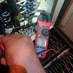
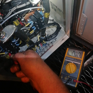
OK video. S
it appears my cheap UNI-T isn't fast enough.
I'll try my fluke


Attachments

  • IMG_20191030_201756.jpg
    118.9 KB · Views: 35
  • IMG_20191031_072938.jpg
    100.9 KB · Views: 30
Last edited:
The Albright contactors S1 and S2 use magnetic blowout techniques to improve their ability to break high dc currents quickly as in your application. It is important that the high current contacts are connected with the correct polarity - one of the two NO contacts will have a + beside it.

Secondly, being dc coils, I wonder if the energisation of S1 and S2 is augmented by permanent magnets in their construction - making them magnetically polarised. In which case the polarity of the dc applied to the coil will matter. I suggest you check the polarity and way the connections have been made to S2 by comparing with S1 and using your DVM; try swapping over the connections to the S2 coil.
 
Could do with seeing the full diagram,of the contactor drawing. They seem part parallel and part sequential.
I take it this is generation,and not a train? how old is the unit,and does it have LOP control?
 
The coils are parallel in the dwg, OP says they are, he's even tried paralleling them with new bits of wire. The fault stays put when the contactors are interchanged or exchanged for different ones. Therefore it seems to be something to do with the physical position e.g. magnetic interaction, possibly indicating marginal operation so that something that shouldn't normally make a difference now does.

Suppose there is a high-resistance connection and once the motor circuit closes the voltage falls to just barely enough to hold the contactors. Now suppose something is either helping S1 stay in, such as a steel casing component behind it bolstering its magnetic circuit, or something is hindering S2 staying in such as magnetic interference from a contactor adjacent. Normally these factors wouldn't affect operation but the marginal holding volts amplifies the difference. Or, as Marconi says, the polarity of S2 is wrong but I don't recall these being PM assisted.

It's all a bit far fetched given that the pull-in is 66% nominal, and drop out 10%, so there's a huge margin of hysteresis to keep it in once it's in. But I am looking for anything that doesn't violate laws of physics.

Scope trace of coil volts would be good! Also, it would be interesting to know what happens with the motors fuse out and the pull-in coils disconnected from the motors and connected in series. This would allow it to get to the point the motor load comes on to the battery, without that actually happening. Would need to keep the test brief or break the pull-in coil connections once in, to stop them cooking. Also need to make sure they actually go in and don't stick with the pinion teeth out of mesh as the motors won't be trundling round as they reach the ring gear.
 
Just thought of another worthwhile check,the drawings show a simplified layout of the two contactors,which does not always correlate to the fact they are handed.
They are,as marconi mentioned,polarity critical,in their operation,so well worth checking the markings.
 
Hmmm never thought of the coil being polarity sensitive (I'm more and ac rather than dc guy)
Certainly something to look into.

Its got to be something stupid.

I thought I found something earlier, the link between SW and 228 on solenoid 1 was wired to 227, but alas still the same when I changed it. :(


I'll keep you posted on this absolutely mystifying problem. In 20 years of being an industrial spark I've never come across anything quite like it.
[automerge]1572525749[/automerge]
The Albright contactors S1 and S2 use magnetic blowout techniques to improve their ability to break high dc currents quickly as in your application. It is important that the high current contacts are connected with the correct polarity - one of the two NO contacts will have a + beside it.

Secondly, being dc coils, I wonder if the energisation of S1 and S2 is augmented by permanent magnets in their construction - making them magnetically polarised. In which case the polarity of the dc applied to the coil will matter. I suggest you check the polarity and way the connections have been made to S2 by comparing with S1 and using your DVM; try swapping over the connections to the S2 coil.


I think you might be on to something regarding the magnetic blow out of the contactors. (I've never seen nor heard of such a thing before) but it could be that the starter motor itself has a short, which is making the contactor force itself open, but the pull in of the coil is still in effect so it pulls the contact close again. Repeating itself until the other starter motor gets the engine running.

That could also explain the massive arcs you get on S2 when it pulls in. Where S1 doesn't.
I'll see about getting the starter motors changed. (apparently 3000quid a side :))
 
Last edited:
Please can we see the coil volts at the coil terminals. Pleeeeease!
 

Reply to Problem with contactors wired in parallel in the Electricians' Talk area at ElectriciansForums.net

OFFICIAL SPONSORS

Electrical Goods - Electrical Tools - Brand Names Electrician Courses Green Electrical Goods PCB Way Electrical Goods - Electrical Tools - Brand Names Pushfit Wire Connectors Electric Underfloor Heating Electrician Courses
These Official Forum Sponsors May Provide Discounts to Regular Forum Members - If you would like to sponsor us then CLICK HERE and post a thread with who you are, and we'll send you some stats etc
This website was designed, optimised and is hosted by untold.media Operating under the name Untold Media since 2001.
Back
Top
AdBlock Detected

We get it, advertisements are annoying!

Sure, ad-blocking software does a great job at blocking ads, but it also blocks useful features of our website. For the best site experience please disable your AdBlocker.

I've Disabled AdBlock