Currently reading:
Problem with contactors wired in parallel

Discuss Problem with contactors wired in parallel in the Electricians' Talk area at ElectriciansForums.net

Re# 29: That could also explain the massive arcs you get on S2 when it pulls in. Where S1 doesn't.

I have just phoned the technical department at Albright who make S1 and S2. I was told the coils do not have any sensitivity to polarity - but I would still see if it made a difference.

I asked about the nature of the arcs if the polarity at the high current contacts was the wrong way round. The magnetic arc quench mechanism expels the arc away from the contacts when the polarity is correct. When incorrectly polarised, the arc is drawn inwards causing damage to the high current switch mechanisms.

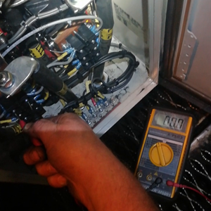
AS you observed a difference in the intensity of the arcs, the brighter display of arc appears correct for S2 and possibly is dimmer on S1 because of incorrect contact polarity. So check by voltage measurement and markings on S1 and S2.
 
Could do with the drawing showing all four contactors,as that drawing shows battery voltage being switched,not 110v DC.
[automerge]1572560512[/automerge]
Also,does this have pneumatic start option?
 
Last edited:
hmmmnz: Re-reading my notes of the call I made to Albright, the technical said that the SW200A-33 is bespoke to original equipment manufacturer by which I assume he means whoever made the controller to start the diesel engine you mentioned. He thought it was a type used in railway locomotives. I have been unable to turn up in any search or dc contactor catalogue the SW200A-33 nor anything when searching against the Coil type 17-167 Ohms and Coil 00V.

What I wonder those is if you have the correct type of dc contactor for the S1 and S2 role because there are a myriad of variations of the SW200 type. Have you a parts list you can check against? And, I have to ask are the substitute contactors both the same part number? And identical to the ones removed?

When I studied your video clips I can't say I thought the voltage readings were unexpected - a dip in voltage as the SMs are energised and start turning, a gradual rise in voltage and then a brief reading of 170V as the SMs and the S1 and S2 are de-energised. An AVO across might show better the voltage v time across S1 and S2. Even better if you could insert the AVO in series with the coils of S1 and S2 to measure the current v time.

The SW200 can be bought with different spring stiffnesses to increase the rapidity of opening the contacts. Stiffer springs mean more power is required from the coil and thus Ohmic heating which in turn affects the duty rating of the contactor. The stiffest spring is fitted in those contactors which have the lowest duty rating. This would seem appropriate for contactors switching high current inductive loads at 110Vdc only used occasionally as in starting an engine. I wonder then if the contactor in the S2 position you are fitting have a coil which cannot provide sufficient force to pull against the spring and make a tight closure of the high current contacts - leading to the arcing - which will modulate the 110V dc supply voltage - which will modulate the current through S2 (and S1) and thus some variation in the force which is closing the contacts. And superimposed is the cranking current pulses as the piston - cylinders are compressed.

See under D and 'Duty' in:
Glossary - Albright - https://www.albrightinternational.com/glossary/

So some higher resistance in the wiring to S2's coil resulting in reduced current through S2's coil? I'd be taking a good look at the ring crimps to S2 coil and even swapping them for some new 1.5mm2 say temporarily.to bowl out dodgy paralleling wiring.
 
Last edited:
Could do with the drawing showing all four contactors,as that drawing shows battery voltage being switched,not 110v DC.
[automerge]1572560512[/automerge]
Also,does this have pneumatic start option?


The drawing shows all 4 contactors.
Scc1 Scc1 S1 and s2 are the 4 contactors in the start circuit. The batteries are 110v dc
No pneumatic start option is fitted

What I wonder those is if you have the correct type of dc contactor for the S1 and S2 role because there are a myriad of variations of the SW200 type. Have you a parts list you can check against? And, I have to ask are the substitute contactors both the same part number? And identical to the ones removed?
Yeah these are identical to the ones removed, and supplied for this job.
I've substituted the contactor from S1 and the old contactor into S1 position, they all react the same way


Watch the video on the previous page. That's as good as I can get with the 2 meters I have available
Considering S1 pulls in fine and it's wired I parallel with S2 I doubt the voltage is the problem
 
Hmmmnz: Yes, not a voltage problem but maybe a reduced current problem through S2. Have you/will you substitute the wire links which places S2 in parallel with S1? It is not unknown for a wire to be overcrimped inside the crimp and break in such a way that there is no metal to metal contact for current flow or which produces higher resistance.

Could you place one of your DMM's in series with S1 and the other with S2 and compare the coil currents please?

And to humour me, could you swap over the polarity to S2's coil.
 
Last edited:
The drawing shows all 4 contactors.
Scc1 Scc1 S1 and s2 are the 4 contactors in the start circuit. The batteries are 110v dc
No pneumatic start option is fitted


Yeah these are identical to the ones removed, and supplied for this job.
I've substituted the contactor from S1 and the old contactor into S1 position, they all react the same way


Watch the video on the previous page. That's as good as I can get with the 2 meters I have available
Considering S1 pulls in fine and it's wired I parallel with S2 I doubt the voltage is the problem
Thanks for posting the videos to the forum! - What a star. You're possibly the first genuine person to post a video (apart from me for testing). So this will go down in history for the forum. :) Thanks.
 
es, not a voltage problem but maybe a reduced current problem through S2. Have you/will you substitute the wire links which places S2 in parallel with S1? It is not unknown for a wire to be overcrimped inside the crimp and break in such a way that there is no metal to metal contact for current flow or which produces higher resistance. Could you place one of your DMM's in series with S1 and the other with S2 and compare the coil currents please? And to humour me, could you swap over the polarity to S2's coil.

I've got another set of wires doubling up the parallel circuit. But it's wired positive to one of the contactors and the negative to the other with the loops in between. So if it was that it'd also take out S1 contactor as well.

I'll flip the polarity on the coil now and see if it makes a difference
 
hmmmnz: I have asked Albright to send me the datasheet for your contactor. Watching your two videos we can see the voltage dip down to 50V in one clip and 60V in the other.

The force of a solenoid is:

F = (n x i)2 x magnetic constant x a / (2 x g2)

where n is number of turn, a is area and g is length of air gap. So, the force is proportional to the current squared or to the applied voltage squared if the coil resistance R is constant.

What this means is the the relationship is parabolic:

parabola.gif

where y is force F and x is current I.

So, the force produced by the solenoid(S1/S2 coil) increases more rapidly as the magnitude of the current/voltage increases; or the force decreases more rapidly as the magnitude of the current/voltage decreases. The effect then is if the coil of the contactor S1/S2 is first energised with a low voltage the pull in force will be lower than at a higher voltage - the contacts may not then close with sufficient force to make a good enough conduction region for the starting current. Some arcing will occur tending to push the contacts apart which reduces the starting current a little and at the same time increases the applied voltage to the coil - the contacts are then pulled together with a slightly greater force. The starting current increases once again but the contacts are not made well enough so there is some more arcing tending to push them apart. This 'hunting' continues until the start current has dropped to a sufficient level that the contact pressure can pass this current without arcing.

The long and the short of it is I wonder if the problem is not S2 per se but the out of specification drop in applied supply voltage because:

1. The 110V battery is not fully charged.
2. The battery has aged so its internal resistance has increased limiting its ability to provide high current without excess volt drop.
3. There are some high current supply (+ and -) conductors which have poor connections including on the battery.
4. The starter motors have faults or are struggling to start the diesel for some reason.

Quite why the problem only occurs for S2 I suggest (don't know) is because of some magnetic interaction between S1, S2 and the magnetic fields around the high current conductors which tends to promote the hunting effect for S2 but not/not as much for S1. Or the polarity matters in the sense it can reduce or aggravate hunting.

Can you charge up the 110V battery to see if it has an effect on the problem?
[automerge]1572605355[/automerge]
I have to go out now but here is what I have from Albright:

Type: SW200A-33

Coil Voltage (V) 72 INT DC

Coil Resistance (Ohms) 167

Pull In Voltage (V) 50.0 Maximum

Drop Out Voltage (V) 16.0 Maximum

Coil Power Dissipation (W) 31.04

Additional Features

RED ADHESIVE DOT POSITIONED ON FRONT OF TOP COVER , SAME SIDE AS

3-WAY TERMINAL BLOCK - SEE DRAWING 2155-113.

SPECIAL LABEL FITTED STATING COIL RESISTANCE, SEE DRAWING 2155-113.

SOCKET SET 2BA GRUB SCREWS MUST BE USED TO LOCK AUXILIARY PLUNGER.

All figures above are stated at 20 degrees Celsius
 

Attachments

  • sw200A-33.pdf
    250.1 KB · Views: 2
Last edited:
Hi just what type of 110v dc starters are fitted?
All the ones i have dealt with have been 24v dc,and/or pneumatic start.
 
I expect the starters are 48V (ish) as there are two in series, no?

What is the rated voltage of the coils on S1 & S2... 72V? If so, according to the Albright bumf the drop-out voltage is 16V. We can tell from the way the engine accelerates despite the interruptions that the battery voltage and internal resistance must be at least fairly OK and would not cause the voltage at the coils to drop anywhere near 16V otherwise it simply wouldn't turn over, and/or the solenoids wouldn't engage. So I think we can rule out that end of things.

That is not to say the voltage at the coils is not falling to 16V. There can be many interfering factors but no factor is as important as the supplied coil voltage in deciding whether a contactor holds or drops out. OK, strictly speaking the current, but for a quick check we can look at the voltage and accept that the resistance of every contactor that's been tried is not going to jump up and down rhythmically in the same way. If need be, we can then look at the current to confirm a diagnosis.

As yet, I don't think we have actual figures at S2's terminals at the moment it first pulls in, when it drops out and when it pulls in again. IMHO, trying to diagnose without knowing these, is working somewhat blind. If the coils are only getting 20V when S2 drops out, then whatever the difference is between S1 & S2, they are operating completely outside their spec and are entitled to do whatever they please and be influenced by any and all external factors. If it is 60V, then the problem is definitely with the physical position and load in the S2 position as it should be holding in perfectly well.
 
Hmmmnz: In #23 the image of the connector block wiring does not look the same on the right(S2) as on the left(S1). For both S1 and S2 only the aux NC contacts are used in series and as part of the logic for controlling SSC1 and SSC2. The two browns into the bottom left of S2 look odd to me if the contacts are to be in series - I'd have expected a brown bottom left and bottom right of S2.

There should be no external connections to the middle pairs of terminals (from the NO contacts) - it looks like there might be for S2. S1 looks like just the leads from the NO contacts.

Listening to the videos the regular arcing/ticking makes me wonder if S2 has its coil fed via its own aux NC contacts so that when S2 closes, after the contact plunger has moved sufficiently, the aux NC contacts open removing power to the coil, so S2 opens...and then repeats the sequence repeats.

Just some thoughts ...

:)
M
 
Last edited:
Yes,this was my reckoning in post#26 :)

But i don't yet know if it's a train,has LOP control,or what set-up the starters are...;)
 
PEG: Albright told me the SW200A-33 is generally found in the locomotive industry. It is not on general sale. The engine is a 16 cylinder producing circa 125kW per cylinder (16 a 100 = 2MW). The IC125 had two 1MW DGs so I don't reckon a it is for a twin power car express train - perhaps a freight train loco? There is a compressor shown on one of the diagrams - HP air for the brakes?

I reckon there are one or more wiring faults of the type end A should go to X and the other end B to Y - but does not - it goes to Z........And this includes the wiring for the SW200A's aux contacts. So some careful wire and connection checking against the wiring diagram is in order methinks.

Lucien said it earlier so credit to him - we need to be mindful it may not we wired up in accordance with the wiring diagram. If it was wired up correctly the series/parallel symmetry of the wiring diagram makes it very hard to come up with a way the problem is located specifically at the S2 position and not associated with the SW200A contactors and their AUX contacts. Because the engine starts it may be an original defect too which has been overlooked.

I look forward to the diagnosis and reckon Hmmmnz deserves a good Scottish malt as his reward. Edinburgh is too far for me to travel to :)
 
In my #34 I mentioned the cranking current pulses:

Relative compression - diesel - https://www.picoauto.com/library/automotive-guided-tests/diesel/

The cranking current/starter motors current waveform is an analogue of the variation on torque required to undertake suck-squeeze-bang-blow of the diesel cycle in each cylinder. I am no expert in how quickly big diesel engines like the MTU should run up but wonder if the recordings you made indicate it is laboured and longer than normally expected? If it was more laboured the current peaks would be much higher, stressing the S1 and S2 contacts, and causing them to arc in rhythm with the peaks of the cranking waveform. Now, it may not be an engine problem causing the laboured start rather one (or both) of the starter motors is faulty in some way. So, if you find nothing wrong with the starter box I recommend you investigate the starter motors as you thought of doing earlier. The initial volt drop from 110V to 50-60V seems excessive to me too so I would still check the goodness of all the high current connections.

DC series motors in series sometimes have two pairs of brushes running against the commutator to ensure continuity of current through the two motors which might not happen with only one pair in each. Easy to check the brushes are in good order.

It would be informative to measure the cranking current and the voltage across each starter motor to see if one motor is showing any difference to the other.

Last (for now :) ) could it be that one motor is not engaging the flywheel so the other is doing all the work?
 
No much of an update, I've gone through all the wiring again. Everything is going to and from where it's supposed to, I've meggered everything to earth, all good.
Im still waiting on MTU changing out the starter motors and solenoids. (they won't just give to me to fit, so I'll just have to wait)
I've plenty of other testing to do. And currently the power car starts and runs, so I can carry on (good detective work figuring out its a train) its a class 43 hst.

I've checked the wiring against other trains, and it's the same.

It pretty much leaves me with the solenoid /starter motor being the problem. As to what that problem is. ...

I'll keep you posted, they are supposed to be changing them out tonight
 
I'm not sure how we actually got to reasoning that the starter(s) are faulty without actually checking their performance, or has that actually been done? I'm not that familiar with rail traction applications and I'm sure the OP is, but for a large diesel, given the lack of constant motor power, this start doesn't sound too far off the mark that I would immediately suspect them. I would certainly want to see current readings that are significantly too high before splashing out on new ones.

Last (for now :) ) could it be that one motor is not engaging the flywheel so the other is doing all the work?
The main contactors don't operate until both the solenoid contacts are closed, which indicates the starters are both engaged. A disengaged series connected starter would be massively overspeeding, I think you would know about it.

The cranking current/starter motors current waveform is an analogue of the variation on torque required to undertake suck-squeeze-bang-blow of the diesel cycle in each cylinder

It's a 16-cyl, so the torque ripple at the crankshaft is pretty low, and much higher in frequency than the contactor impulsing.

One test that I didn't mention, that I would have done in the absence of a fast enough meter or scope to follow the coil voltage accurately, would have been to get a filament lamp - a string of 24V lamps if necessary - and watched it that way. Then, the same at the battery terminals on the panel, and at the starters etc. The filament lamp has multiple uses as a troubleshooting tool, especially as a series limiter for SMPSUs and DUTs that might go into runaway or short during test.
 
I'm not sure how we actually got to reasoning that the starter(s) are faulty without actually checking their performance, or has that actually been done? I'm not that familiar with rail traction applications and I'm sure the OP is, but for a large diesel, given the lack of constant motor power, this start doesn't sound too far off the mark that I would immediately suspect them. I would certainly want to see current readings that are significantly too high before splashing out on new ones.
basically ive ruled out everything i can at my end, so starters and solenoids is the next thing in line, it may not be the most scientific or technical way of going about it, but hey ho. there it is.

i dont know if you noticed the resistor bank on the drawing in series with the starter motors i presume that would do the same as a string of lights, im not sure where you are going with switch mode power supplys or why i might need to limit them, (i guess i missed something in the previous posts)

any way, ill let you lot know, if im still paddling up ---- creak after the starter motors have been changed, if it does sort it ill see if i can get them and pull them apart to see what have failed or possibly caused the problem.
 
im not sure where you are going with switch mode power supplys or why i might need to limit them

Nowt to do with your job, just singing the praises of the humble filament lamp as a multi-purpose troubleshooter and problem solver. In your predicament I might have hooked up a suitable lamp across the coils to get a clear, reliable and fairly responsive visual indication of the depth of the fluctuations in the feed to the contactor coils. A 100W 230V gasfilled GLS has the same order of time constant as a DMM bargraph but it's immune to noise, true RMS over any waveform and any frequency from dc to MHz, and leaves your DMM free to take another measurement while watching the lamp out of the corner of an eye.
 
Caution, rather Fermi...

Probability that starters are actually OK = 25%
Cost of Fluke Scopemeter £1250
All-in cost of calling OP to site £100/hour
Time taken to set up scopemeter and take readings at coils, starter resistor bank (to indicate current) etc. 15 mins.
Time of typical train journey=90 mins

(6k-1250-15/60*100)*0.25*90/15=£28350 + all variable operating costs (slightly<£20205) saved in the duration of one journey, i.e. further testing before replacing starters is more cost-effective than running the train.

The big plus, though, is that the OP gets a free Scopemeter :)
 
One of the best threads for a while this one.

Apart from the one about the answers to exam questions obviously.
 
Well she's running properly again. The starters got changed, started with A bank solenoid and starter
And sure enough it ran perfectly.
They decided to change B bank one as well. As they were both changed 3 months ago.
Hopefully I'll find out what the failure point of the solenoid/starter was.


There was no way in hell they were going to buy me a scopemeter, the railway would rather replace 20k worth of components "just in case" than have an absolute that a given problem was the problem.


Many thanks for all the input, and ideas and some pretty awesome spec finding.

Much appreciated.

I'll keep you posted if I get any info from MTU regarding their starters (also the railway doesn't have to pay for them, now they have been the failure point)
 
Hmmmnz - your initial hunch, after careful elimination of other possibilities, was right. Well done Sir. Good engineers, of which there are many Scotsmen, have this sense of what is probably wrong. In your case the starters are very stressed, frequently - electrically and mechanically - which is not good fro reliability.

:)

M

PS: Lucien Nunes, if you ask him nicely, will write you a business case for a scope meter albeit one that does not use his last dubious Fermi estimate ;-)

A Markov chain analysis using expected cost outcome after a some Monte-Carlo runs would be more persuasive.
 
Last edited:
Lol. I'm sure there are lots of great Scottish engineers... I'm not one of them... Being a kiwi ?
But sometimes you just have to rule out everything you can with the tools available to you and swap out the rest.
Its certainly been the weirdest electrical problem I've come across, and I'm still not sure what exactly went wrong. I hope I get some more info from MTU.
 
it can only be one of two things,
1 - coils not receiving correct power, / so a volt meter should findthat one out !
Or
2 - the contactor has developed a fault / In which case I would also replace them both.
 
it can only be one of two things,
1 - coils not receiving correct power, / so a volt meter should findthat one out !
Or
2 - the contactor has developed a fault / In which case I would also replace them both.
Lol. A few months too late, and it was neither the contactor or a voltage drop.

If you go back through the thread you'll see the videos.
 

Reply to Problem with contactors wired in parallel in the Electricians' Talk area at ElectriciansForums.net

OFFICIAL SPONSORS

Electrical Goods - Electrical Tools - Brand Names Electrician Courses Green Electrical Goods PCB Way Electrical Goods - Electrical Tools - Brand Names Pushfit Wire Connectors Electric Underfloor Heating Electrician Courses
These Official Forum Sponsors May Provide Discounts to Regular Forum Members - If you would like to sponsor us then CLICK HERE and post a thread with who you are, and we'll send you some stats etc
This website was designed, optimised and is hosted by untold.media Operating under the name Untold Media since 2001.
Back
Top