Search for tools and product advice,

Discuss Van Wiring System Off Of Leisure Battery in the Auto Electrician Forum area at ElectriciansForums.net

Reaction score
1
Hi guys,

So basically I'm coming here looking for some friendly advice with the intention of eventually getting an electrician out to make sure I'm not messing anything up (I'm based near Swindon - recommendations welcome!). I just want to do as much of the prep as possible.

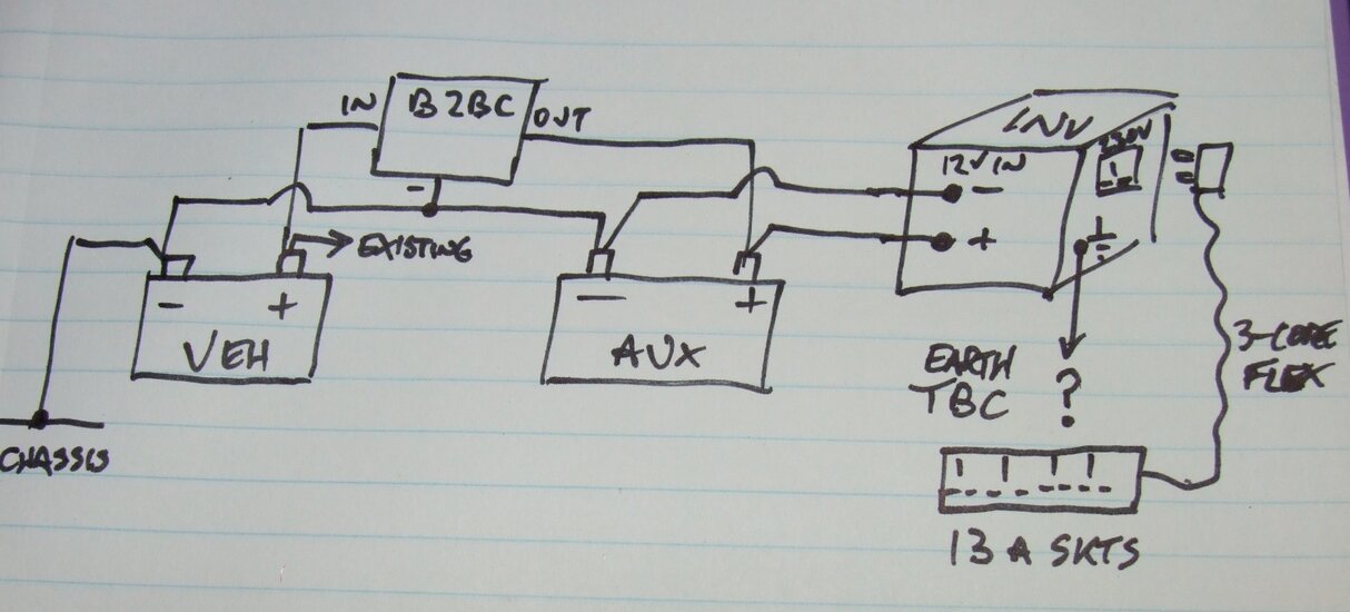
I've put together a wiring diagram based on what I've learnt on the web. The van is an LDV Maxus and the starter battery looks like the best thing to plug in to as the alternator is hidden away. Basically what I want to do is hook up some LED lighting and a couple of mains plugs which I can run laptop/charge camera batteries/phone etc from. The only thing I've bought so far is the 85ah leisure battery.

Based on the diagram could you kind chaps let me know if:

a) anything is going to cause a problem?
b) if anything could be improved? (I've read that the split charge relay isn't the most economical solution, but am struggling to find a replacement)
c) how I would go about working out what wires/fuses I need?
d) what size inverter should I choose? Is this even the best solution?
e) have I missed anything?

The other thing I was wondering was about the leisure battery. If using up a full charge is going to ruin it, is there some sort of mechanism I can implement to prevent this happening?

Thank you so much for your time and effort,
Scott
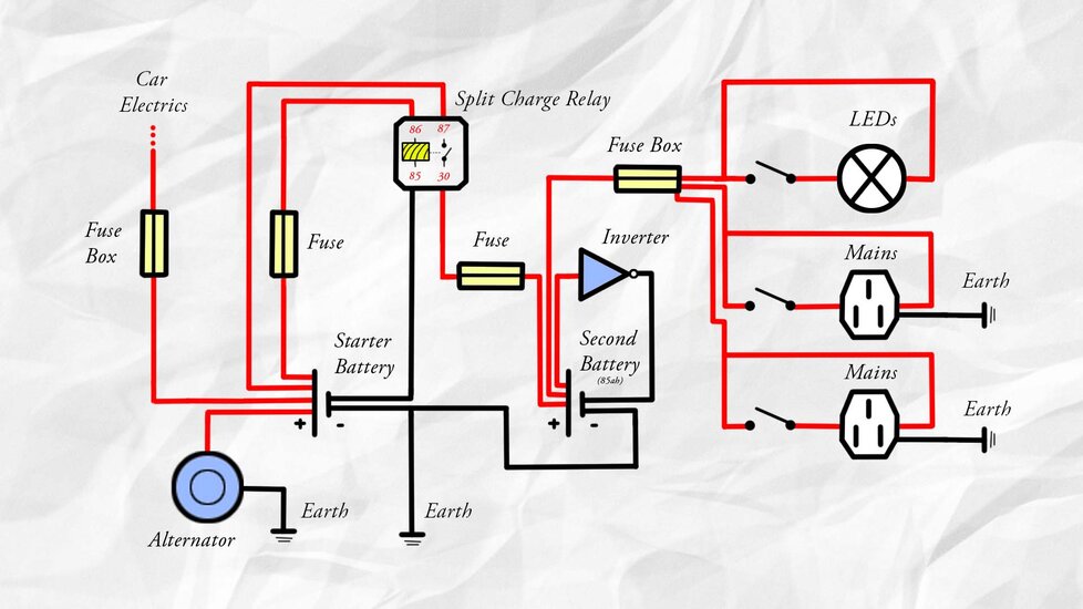
Wiring Diagram.jpg
 
The principle is OK but there are some bugs in your sketch there.

The coil of the split charge relay is shown as being permanently energised from the battery, i.e. the relay will stay closed instead of isolating the batteries as required. If you intend to use a straightforward relay, it should ideally be energised from the warning lamp output of the alternator (if it's machine excited) so it closes when the alternator is delivering output. If it doesn't have a suitable output, next best is an ignition feed that's off during starting, so that the batteries are linked when the engine is expected to be running. If you are intending to use an electronic voltage sensing-relay, this will do the switching automatically according to the engine battery voltage - it won't need the extra control feed.

The fuse in the relay contact circuit is unlikely to do much good, it might blow on the brief current surge when the batteries connect at different states of charge, and its resistance is undesirable. In fact the resistance of this part of the circuit should be kept very low.

I'm not sure why you've connected the mains sockets to the 12V circuit! Note also that the 'earth' of the mains sockets is a different animal to the 'earth' (i.e. chassis negative) of the 12V circuit. Keep mains wiring to a minimum and connect all three cores to the plug that is plugged into the inverter, not the chassis. There is a whole separate discussion you can have over earthing the inverter output. much advice will be wrong. Search this forum for info.

I had to laugh at the inverter symbol... that's the symbol for a binary logic inverter, not a box that converts 12V into mains!

Your q's:
a) As above
b) Voltage sensing relay to control split charge
c) Depends on loads you want to run and length of cables
d) From your description, a few hundred watts would be sufficient. A 600W unit would have an easy life without being much more expensive.
e) The devil is in the detail
f) The inverter will have under-voltage shutdown to prevent you over-discharging the battery, but it will not prevent you using it to 100% depth-of-discharge. Big expensive units allow you to set that limit too, but you might choose to add a voltmeter and just keep an eye on it. Voltage tracks charge state over a limited range and at low load, although varies with temperature. Once you get a feel for the available energy on (say) 60% discharge you can stop watching the VM. OTOH it's not a huge deal, one can spend too much time fretting about battery cyclic life instead of drinking beer and partying!
 
Pretty well covered by Lucien...small gripe would be the use of a 1960's split charge relay,in amongst all that 21st century tech:)

Your vehicle alternator will "see" those two paralleled batteries as one,and let the charging shananagins begin...

That relay will open the lock gates,even if the water level the other side,is 10 foot higher than your barge...and another holiday is spoiled ;)
 
I'd like to see you open the gates against 10'. The most I can manage is a couple of inches!

If the alternator is retrofitted with an intelligent or battery-sensed multi-step regulator, then I agree that paralleling batteries in different states of charge with a relay may not be desirable. But with a standard constant-voltage regulator I don't see much harm in it. The alternator will simply hold all of them at 14.4V or whatever, regardless of how many or their state of charge. If the aux battery is flat there will be a brief equalising current when the relay closes, not as much as one might imagine, and not enough in practice to damage the relay. I fitted dozens of Bosch 0-332-002-156 on systems with 200-300Ah and never knowingly had a failure. The relay serving the general domestic battery on my boat sometimes has to pull 440Ah of fairly-low and 300Ah of fully-charged batt together, it's only a basic Lucas SRB600 and it's lasted 20 years so far.
 
Thank you for the information - it's immensely valuable!

So, I have readjusted the diagram based on what you have said to the best of my ability. I'm still not really sure where the inverter should be connected & have struggled to find information on wiring up the VSR online, so there may again be errors... If you could be so kind as to take another look? :D

Another thought - if I wanted to add another leisure battery into this system would that cause problems?

ps if I'm seeing 10' of water outside my van then the electrics will be the least of my problems haha!

Wiring Diagram.jpg
 
Remove the fuses from the relay leads. Give the relay a negative reference from the starter battery. The inverter is a box with 12V DC in at one end and 230V AC out at the other. Job done.
 
Here is some further information on the situations in modern vehicles with smart alternators.
Maybe not applicable in your situation , but may be of interest in general.

One thing to remember is that high and low voltages outside the tolerance of the ECU will cause problems
If the battery is+/-of the tolerance for instance the ECU will not open the injectors. You would not even be able to start the vehicle with a tow until the parameters have been satisfied.

http://www.12voltplanet.co.uk/auxiliary-battery-charging-in-vehicles-with-smart-alternators.html
 
I was thinking of a 600W continuous rating as being around twice the maximum power you were implying you might want - a laptop adaptor taking 120W (flat laptop batt) and a few other small electronic items at 50W each. Small battery chargers may not take this much and a fully charged laptop might only require 40W to keep it running. Do you have a definitive list of things you want to power?

Sizing cables depends on both current rating and voltage drop - the cable must be large enough to satisfy both requirements. Voltage drop depends on length and is very critical in 12V systems - for the same percentage loss at the same power consumption, cable resistance needs to be 400 times lower on 12V than 240V. With a battery discharged to 11V and an inverter efficiency of 85%, a 300W load will require 300/0.85/11=32A from the battery. Unenclosed 4.0mm² might appear to be adequate for current rating, however if the inverter is 3 metres from the battery the voltage drop would be 32 x 0.018/4 x 2 x 3 = 0.86V which is excessive. You might do well with 10mm² for the charging leads and the inverter, and probably 1.5 for the lighting, but you should check the numbers when you know the lengths involved.
 
I see, I see. My laptop charger reads 85W & battery is around 15W if I remember correctly. Aside from this, just the LEDs, which would probably max out around 20W. I can't see anything more watt intensive than my laptop being used - especially not at the same time as my laptop and I don't own/plan to use much other electrical gear. The initial surge seemed like the only thing that could cause problems, but I couldn't actually discover if a laptop has this phenomenon.

Inverter should be adjacent to the leisure battery & both should be around 1.5/2m from the starter battery. Lighting may run up to 3m and mains plugs should be >1m, but I think using the information you've provided I should be able to google around work it out - thanks for spelling that out for me - immensely helpful as ever. :D

Out of interest, what are the cons in using wire that is too thick? Extra resistance?
 
The main disadvantage of oversize cables is that sometimes they can be difficult to connect to the device terminals. It's self-defeating to use a really heavy cable but then make a poor connection that develops high resistance. Other than that, and within the bounds of sensible cost, bigger is better although the benefit diminishes exponentially once the voltage drop is below a few %.

Surge is negligible for the laptop adaptor. It sounds like a 300W inverter might be adequate for your very modest requirements then. Many of them are built right down to a price and not generously proportioned inside, so it pays to allow a bit of headroom. They contain highly stressed electronic components and have a high failure rate per hour of use when pushed to their full output.

Are you running the LEDs from the 12V circuit? You should be, unless you require some special type of fitting that can't be got in a 12V version. But from your wording it sounds like you are including them in the inverter output i.e. using a 230V driver or adaptor to feed them. This is inefficient - transforming the voltage up and down again - and might add 30% to their consumption from the battery.
 
Great tip on the LEDs. I did not realise that. So I can wire it directly to the leisure battery with a fuse in between?

I plan to be using the inverter almost daily, so maybe something a bit more heavy duty would be a good idea then.
 
Hello again! So, after some research and consideration, I think I'd like to go for a battery to battery charger for the increased charge times. From what I can gather I would just replace the VSR with the B2B - is this correct? Is there anything else I should be mindful of. Many thanks.
 
Decreased charge time, surely! B2BC's used to be expensive but are perhaps better value now and the better charging performance worth the investment. I still tend to think in marine terms where an engine might run for 12 hours a day and there might be charging current available from somewhere - genset, aux or propulsion, for much of the daily load cycle. As such it's not so important to get charge into the service batteries quite as fast. In wiring terms the only real difference is that it will require more substantial negative connections than the low-current sensing wire of the relay. It will also probably require free airspace for cooling.

OT but does anyone remember Lucas 4BD split charge diodes in oilfilled cans like ignition coils? Found a few of those in my old service stock the other day dating from the mid 70s, including a pos-earth (common cathode) one. Only any good with a battery sensed regulator of course, and sure enough there were battery sensed 4TRs, 14TRs etc in the kit. And even a NOS 3AW warning light relay for the venerable 11AC. But I digress...
 
Right you are... decreased charge times. Airspace and good connections - got it. Cheers again Lucien. Your second paragraph, however, is literal gobbledygook to me!

Those LEDs look perfect. Not sure about he 20-40day delivery though - don't still have some lying about you fancy selling do you ha?
 
great deals in China on 12V leds...

http://www.aliexpress.com/item/20PC...ite-Red-Green-Blue-Waterproof/1896145024.html

bought a lot of 50 some 2 years ago, got them all over the workbench, back of the van, some in mates shed, all still work no problems.
runs of straight 12v dc, happy with 14v in the vehicles too no drivers needed
and fix anywhere with 2 little screws no sticky tape mess.
Do you buy much stuff from there?

I've used www.dhgate.com a few times but most of it seems to be tat you'd see at a car boot sale.
 
Almost installation day! Couple of things still bothering me if anyone would be kind enough to clear them up.

1. I understand that I can wire the earth for the battery to battery charger (and both batteries) to the van's chassis, but not the plug socket earth cables. How do I ground them?

2. What's the best way to attach the cable to battery positive/negative terminals? Do I simply screw it in? (something like this https://www.amazon.co.uk/Car-Batter...8&qid=1474736934&sr=8-1&keywords=car+terminal)

3. If I have 4 wires coming out of the inverter into the fuse box does it matter if they overlap? ie. have four wires connected to the same terminal? Is there an alternative? As well as these 4 wires I'll also have the cable coming from the start battery to contend with. I can foresee there not even being enough space to connect everything.

Thanks as always.

Wiring Diagram.jpg
 
Decreased charge time, surely! B2BC's used to be expensive but are perhaps better value now and the better charging performance worth the investment. I still tend to think in marine terms where an engine might run for 12 hours a day and there might be charging current available from somewhere - genset, aux or propulsion, for much of the daily load cycle. As such it's not so important to get charge into the service batteries quite as fast. In wiring terms the only real difference is that it will require more substantial negative connections than the low-current sensing wire of the relay. It will also probably require free airspace for cooling.

OT but does anyone remember Lucas 4BD split charge diodes in oilfilled cans like ignition coils? Found a few of those in my old service stock the other day dating from the mid 70s, including a pos-earth (common cathode) one. Only any good with a battery sensed regulator of course, and sure enough there were battery sensed 4TRs, 14TRs etc in the kit. And even a NOS 3AW warning light relay for the venerable 11AC. But I digress...

I do,vaguely,the 11ac was standard on some Jags,and various small Perkins,etc...what a mass of components,compared to today's gear.
Control units,field relays,and a bumble-bees heart of an alternator buzzing away at the end!

I appreciate your scenario re split charge relays,but with limited depletion,and use by your good self,problems would be rare.

In situations where there is not a "dedicated" charge alternator,as such,say just a vehicles standard fitment,and the aux batteries are flattened by a liverie's kid's laptop and lighting use...the 40A it tries to pull when that relay closes,plus the vehicles ancillary use,just murders the poor alternator.

Found one 2 year old MAN 18 tonne truck,with a 45A alternator as standard! Retro-fitting a 120A upgrade,was £850,12A current limited B2B unit was £70,so,customer had change for a new Stubben (saddle)

As a kid,i used to stalk an old auto-electrician,he had a very bad hunchback,and temper to match,but i learned many things...one was his reluctance to clip a Durite ammeter on,when testing charge rates,preferring to ask "can yer keep yer 'and on the casing,more than a couple of seconds?" ...a "yep" would mean no further discussion ;)

As for my lock gate analogy,it IS possible to open them against a filled lock,or the upper level...just requires a Yale strongback or pull-lift,slung across the gate beam ends...don't ask...all i remember was THAT was the easy bit,removing all the old safes and shopping trolleys obstructing the sluices was a messy pain:)
 
Still some confusion there. You do not need a fuse box on the AC output of the inverter, the 230V loads should plug directly into its 13A output socket. Whether you provide any additional AC earthing / grounding depends on how the inverter is internally configured, we cannot answer that without knowing and on small low cost units they don't tend to tell you in the blurb like they do on professional ones. You can test it with a meter.

The term 'earth' in 12V vehicle wiring, such as 'earth connection' or 'negative earth' simply means 'common return conductor' and has nothing to do with safety earthing. Using the vehicle chassis or 'earth' as one pole of the circuit is simply an economy measure to save cable. Whereas the term 'earth' in mains voltage 230V wiring means 'safety equipotential conductor' and has nothing to do with carrying the operating current of the device. Two very different things.

I don't understand your 'four wires' bit at all.

Those battery terminals are OK-ish but the cables need to fill the terminal before you do up the screws otherwise they will just fall out again. There are better versions of the same, or ones with a captive terminal bolt and nut to which you can connect a crimped lug. Or you can get pre-made cables with crimped terminals.

Very rough sketch attached of what I think you're trying to achieve

DSCF4804.JPG
 
Thanks Lucien.

By four wires I mean the two LEDS circuits & two mains circuits. (I realise now I only have one LED drawn, but there will in fact be two on separate switches).

I don't understand why I don't need a fuse - shouldn't each of the LED/mains circuits be fused? Could you kindly explain that to me?

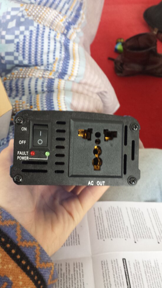
Thanks for clearing up my earthing confusion. How then, shall I earth the inverter? Photo attached.

20160925_181928.jpg
 
Compared to household mains supplies which can deliver thousands of amps in the event of a short-circuit, the maximum output of a 600W inverter is around 2.6A. It simply does not have the capability to produce higher currents, and for its own protection against damage it will shut down if overloaded or short-circuited. The smallest fuse any piece of mains electrical equipment normally requires for adequate protection is 3A, most are fine with being protected at 13A or 16A. As the inverter output cannot reach this level, there will never be enough current to blow such fuses hence no point adding them.

You attach a pic of the B2BC but ask about the inverter earthing. When you have the inverter you can double-check the internal connection of the output socket earth pin by measuring its resistance to the case and DC input negative. There will then be some debate about the best configuration according to what kind of wiring you propose to connect to the output.
 
I opted for a 1200w inverter in the end, as I didn't want to worry about overloading it. So the maximum output would be around 5A and should still be fine. Thanks.

Yeah, I can't explain that one away - it had been a long day! There will either be 2/3m of cable between the starter battery and leisure battery and >1m cable from the leisure battery to the inverter, or it will be the other way round. It depends on how I can rejig the space for the leisure battery under the bonnet.
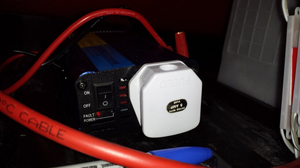
20160926_133700.jpg 20160926_133708.jpg 20160926_133716.jpg
 
I expect that will do fine for your requirements, given the size of the unit and its terminals I would be sceptical about its ability to support 1200W for very long. Keep the cables short and fat consistent with keeping the inverter cool.

If you want to think about earthing on the 230V side, you will need to measure the resistance from the earth contact in that evil multi-hole socket to the neutral contact, the DC input and the case (I note it doesn't have a separate earth terminal.) What you do then will be a matter for discussion, there might not be one single recommended method as there are pros and cons of floating supplies etc. Or you could do what most people do and ignore it completely as an insignificant risk with so few pieces of equipment connected.
 
I missed these - thanks for chipping in. Insignificant risk = no hassle in my books.

Could you clarify what you mean by a distribution point spinlondon? Do you simply mean a means to distribute more sockets etc in the future should I wish to?
 
Okay sure. Logistically, I was wondering how I'm going to turn a single live wire from the fuse box into four and it makes sense to use the fuse box as you suggest, but do I need another part. Like I know you can get 2,3,4 way battery terminals - is there something similar I need here?
 
I'm un-stumped! Managed to figure out a way if I drill a new hole behind the fuse box. I've worked out I'll need around 2.7m of cable to run from the starter battery to the battery to battery charger. Where, conveniently, is a shelf which I should be able to store everything else. So I'm tying to work out cable size:

Max cable current at an inverter efficiency of 85%, 600w max load and battery discharged to 11v: 600/0.85/11 = 64A from the battery.
Volt drop is then a distance of 2.7m, volt drop figure is 2.8v for a 16mm2 cable (from https://www.tlc-direct.co.uk/Figures/Tab4.7.htm) and the 64A from cable current: 2.7x4.4x64A = 0.484. In a 12v system this is just over 4% voltage drop right? If I can find a 3 or 4 core 16mm2 cable then (according to the linked table above) I can get the voltage drop down to 0.414 which should be okay right?

Is there anything else I'm forgetting? Thanks!
 
Hi - just looking at the pics of your invertor in post #25 and LN comments in #26. The manufacturer supplied 12v lead looks like it might be 4mm2. Sometimes the supplied cables can be a bit light duty, but I'm not sure investing in multiple 16mm2 cables will be worth your effort. Your calc of about 0.4V drop for 64A over 2.7m of 16mm2 copper looks about right. But I just don't see that invertor in your pic being able to sustain that draw. Of course I can't read the spec etc so I may well be wrong. If you want, you could try connecting to 12v car battery and loading the 230V AC side with some lamps via a plugboard and see how it performs?
 
There seems to be some confusion here! You say the 2.7m is the length of the B2BC input cable, but you then calculate the VD using the inverter current, not the B2BC input current. As it happens the maximum is a similar figure (60A) but that is only coincidence - they are separate circuits working at different voltages and currents. The B2BC will only be operating when the alternator is running, so the launch voltage at the starter batt should be >14V. So long as the VD doesn't reduce this below the minimum input voltage of the B2BC at 60A, the voltage at the inverter batt will always be correct. Decreasing VD a few more % will simply increase maximum output current from the B2BC by about the same amount so it's not worth busting a gut for.

The VD is likely to be a few % less than the tabulated value because the cables won't be running at full temp, because the current is limited below their CCC by the VD.
 
Hey Wilko, thanks for chipping in. I was thinking 10mm2 for the inverter & leisure battery cables. Think that's about right? The 16mm2 I meant just for the starter battery > B2b charger (and b2b negative cable). Inverter is rated for 600/1200w. I've tested a couple of bits off of the 12v lighter and seems to be okay handling loads up to 300w so far. Can't imagine I'll be loading much more than that.

Lucien, I admit I struggled superbly with the calculations so that would explain the confusion. Although I am getting the gist a bit now after some research & your help. Thanks for clearing things up (again). Would you be so kind as to clarify what you mean by 'CCC'?
 
I would normally use Tri-rated AWG 4 or 35mm2 for battery to starter cables.
Although, that's on Harley Davidson motorcycles, so it may be different for vans and other vehicles?
 
Thanks for chipping in guys. I've started putting some wires in (unconnected) and cutting cables to size. A few questions have cropped up and I would be very grateful for some help. I'll upload pics for ease of explanation.

1. I'm wondering how I am going to take a single live wire from this inverter plug and turn it into two wires for two mains sockets? Also, if I leave the negative/ground for this plug unconnected it shouldn't matter right? The inverter negative will be linked to the battery terminal (from the 12v cable on the other side) I'm technically just using it as a live output from the inverter?

20161012_163423.jpg

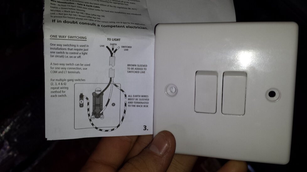
2. What's the best way to hook up this pair of wires? I've noticed in a lot of the circuits in the car there's a clip system. What are these called, as I'm struggling to find these online? Or is there a better way? Should I remove the two wires attached to the LEDs and solder on the 2.5mm2 wire I'm installing?

20161012_163500.jpg

3. Is it best to return the earth (in this instance the negative cable if I'm right?) to the leisure battery negative (which will be earthed to chassis). I remember Lucien saying not to take this to the chassis earth so I'm a little confused.
20161012_165925.jpg
4. This is the B2B charger. In the instructions it says if I 'link' the two connections here labelled 'battery' & 'temp' I activate the feature where the charger turns off and on automatically (pretty desirable right?). By link I assume it means simply connecting a wire between the two with the screw in sockets. Am I right/if so, what thickness should the wire be?
20161012_163658.jpg

Many thanks!
 
Also, I've just opened a thread asking for an electricians help with overseeing the installation at some point over the next week. If anyone in the Swindon (Broad Town specifically) area can help out (or you can recommend someone) that would be great.
 

Reply to Van Wiring System Off Of Leisure Battery in the Auto Electrician Forum area at ElectriciansForums.net

Similar Threads

Last weekend I experienced a weird electrical fault with my 2010 Peugeot Boxer Van. A little background - the van is a 2010 Boxer 330 2.2 Short...
Replies
3
Views
842
Hi, My camper has a new 12v battery and I have wired up a split charge relay with a 100 amp blade fuse near van battery and a 100 amp blade fuse...
Replies
7
Views
2K
I have an 5kW inverter and 48V Lithium battery with inbuilt BMS. As you would be aware, when inverter gets battery power, immediately the...
Replies
0
Views
587
Hello! I'm needing some help. I'm wiring in a start panel, using a spst toggle, and a (momentary?) push button. The idea is to flip the switch to...
Replies
0
Views
608
Hi - On our small vessel we have a 12v failry powerful motor to run the autopilot, where the power is supplied by the boat's battery bank. On an...
Replies
20
Views
2K

OFFICIAL SPONSORS

Electrical Goods - Electrical Tools - Brand Names Electrician Courses Green Electrical Goods PCB Way Electrical Goods - Electrical Tools - Brand Names Pushfit Wire Connectors Electric Underfloor Heating Electrician Courses
These Official Forum Sponsors May Provide Discounts to Regular Forum Members - If you would like to sponsor us then CLICK HERE and post a thread with who you are, and we'll send you some stats etc

YOUR Unread Posts

This website was designed, optimised and is hosted by untold.media Operating under the name Untold Media since 2001.
Back
Top
AdBlock Detected

We get it, advertisements are annoying!

Sure, ad-blocking software does a great job at blocking ads, but it also blocks useful features of our website. For the best site experience please disable your AdBlocker.

I've Disabled AdBlock