Discuss Control Panel for 3ph Heaters in the UK Electrical Forum area at ElectriciansForums.net

J

jparker86

Hello,
I am new to the forum and would be most grateful if anyone here could help me with a project I am working on.

I have a control panel which I have made that controls 2 x heaters and 1 x pump.

Both heaters are 6kW (three phase) and the pump is single phase.

It all works, and I have on/off push buttons to operate the heaters and pump all run via the emergency stop button.

Where I am stuck is that my three phase heaters have a built in thermostat, which switches the contactor from on to off when the heat exceeds x degrees. My problem is that with my current design, unless someone presses the start button again it wont switch back on!

Under my current design, the thermostat isn't installed I left this until last (I underestimated how easy it would be).

Currently, all that happens is the device will turn on and off.

What I want is for the thermostat to cut in and cut off the power to the heater when temperature gets too high.

In my head I am thinking the best idea would be to have a contactor which is controlled via the on/off buttons, and that powers another contactor that is controlled by the thermostat?... or am I missing something that could help me?

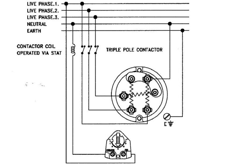
I below attach the wiring diagram for both the heater in question and the control circuit diagram.

Any help would be gratefuly rec'd.
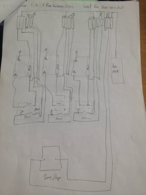
photo.JPG

heater 1.jpg
 
Maybe you just need a rotary type on/off switch rather than one that momentary makes when pressed. I also can't really make out your hand drawing, did you use the aux contact on the heater contactor as a self hold? Maybe that could be the problem.
 
After you've sorted out you wiring issues then you'll find long term operational issues may be you next problem.
More info as others have asked, nature of the job, temperature control (critical to maintain or flexible)
Last thing you want is hunting where the contactor is pulling in and out rrepeatedly as the temp goes over and under the stat setting.
If the heaters are trying maintain a specific temperature which is critical to the job in hand you should looking into P.I.D. controls possibly with solid state switching relays which in turn will require ultra-fast fuse protection (semiconductor fuses) to protect the relays if elements short.

You need to get a detailed list of the nature of the job in hand as its alright us correcting your wiring issue but without knowing more it might not be the correct design for job in hand.

Trying to answer your query you use you start heater buttons to pull in a relay with retaining link that controls feed to the stat, use the stat switch wire to pull in the heater contactor(non retaining)which will pull in and out on demand, the heater stop button will drop out the stat supply relay subsequently dropping control of the heater contactor out.
 
Last edited:
Hello,
Thanks for all your replies.

I looked at the drawing but am I correct in saying their is no "start/stop" buttons for the heaters?

The idea is that the control panel can turn the heaters and/or pump on and/or off, but while heaters are on they maintain a set given temperature.

Do we think the best thing is to remove the start/stop buttons and replace with selector switches?

Jase
 
Again cannot really work out your control strategy but FWIW, i did a 5 heater thermostatically controlled panel, very simple. One thermostat and heaters selected for need. I used 5 contactors (one for each heater) 5 selector switches, one for each heater. On the control side , the thermostat supplied or not control voltage to all heaters selector switches and other side of switch to relevant contactor.
 
I understand you want to bring in a heater by thermostat but thats it. You say the heater has a built in stat but its cutting out and not resetting the contactor.

So this implies, i think, that you have L1,L2L3 to each heater plus a couple of wires from the stat to the control panel where the contactors are ?

Its hard to make out exactly what is where.

Tonys drawing gives you a proper working solution for push button to start the lot and lets each heater be controlled by thermostat.

If you want additional control of heaters, i.e. selector switch, wire them between th1 and k2 and th2 and k3.
 
Last edited:
Hello,

At the moment the stat is not controlling anything. Presently I press start and stop and the heater or pump will turn on. I can have anything on and off at once. For example two heaters on without the pump, and then I want the pump on so I turn that on.

Problem is that I want the thermostat to cut off the heater when the temperature set is exceeded. This is where I am coming unstuck.

From Tony's drawing I see how this works but won't be able to turn the heaters on and off without hitting the e/stop?

For example in this application we might want to just operate a pump without the heaters on at all.
 
Well - its pretty much on a plate, still dont understand how the built in thermostats are dropping out the contactors in the panel.... but hey, had a miserable day fitting an extractor fan - would have loved to wire up a panel today :)
 
Reading the OP hes has wired the stat control to pull in and drop out the contactor, because it dosn't pull the contactor in auto the i assume hes wired the stats in series with the stop circuit hence once stat opens the OP needs to use the start button again.
 
Its all a learning curve we were all their at some point, remember opening and trying to fault my first all in one start/stop contactor in enclosure..... it took an hour to just figure it out, nowadays i find myself following idiots who have connected them up all wrong and strip and wire in 5mins to their annoyance but hey! thats not my fault as they are site sparkies for the companies ..... my experience is the majority of the wing their jobs talking the talk unable to back it up, i got loads that ring me for advice ..... makes me wonder what exactly they are paid for.
 
Just use the stats to switch the contactor coils in and out

Hi people,
I apprechiate each and every reply but I am not familiar with how to read electrical drawings. Something that is simple to you isn't really that easy for me.

The circuit works but just when my thermostat cuts off the contractor, it won't work again once my thermostat asks for more heat unless someone presses the start button.

As I say I can make the thermostat control my contactor but I don't always want my heaters on.
 
If you dont get sorted b4 weekend il draft you up a simplified wiring format that you can follow, dont worry about not understanding them yet you pick it up along the way but if its an interest you'd be good to get a beginners guide to control wiring and schematics just understanding the schematics helps you plan your own wiring better as you are constantly looking at examples.
 
If you dont get sorted b4 weekend il draft you up a simplified wiring format that you can follow, dont worry about not understanding them yet you pick it up along the way but if its an interest you'd be good to get a beginners guide to control wiring and schematics just understanding the schematics helps you plan your own wiring better as you are constantly looking at examples.
That would be a great help. I have today gone and got another contactor but still problem is once stop circuit is interrupted the thing won't work again. Shall I have a go at doing another drawing for you ?
 
OK, try this way, have you numbered the panel wires ?
if so simply list each wire you have in the panel. If not have a go at listing all the wires but its easier to explain what to change if they are numbered

So example

wire 1 - from emergency stop to 110V rail
wire 2 emergency stop to push button (start)

ect ect

include the power wiring and all control wiring.

Maybe we can then say " move wire 3 from a to b... etc

sorry for assumptions - no offence meant
 
Have the start stop button pulling in a main contactor then from one of its poles send the supply out to a switch (on/off) which in turn goes to the stat then the switch wire from the stat to the contactor coil for the heater..... this is pretty much what Tony's diagram shows then repeat for 2nd heater.
I assume your problem is your controlling the same contactor with both a start/stop button and stat control and you stat control is acting as a stop command dropping out the retained contactor, this is why you need a independant contactor just for the start/stop command so it remains energised until either Estop or stop is pressed.

Thanks gents for sticking with me on this one. I know it's annoying talking to someone like me who aint got the first clue but I am not going to let this beat me!
Here is my new drawing which hopfully you can see a bit better. This is just one button, the last drawing had all three but they are all identical in how they work.photo.jpg
 
Have the start stop button pulling in a main contactor then from one of its poles send the supply out to a switch (on/off) which in turn goes to the stat then the switch wire from the stat to the contactor coil for the heater..... this is pretty much what Tony's diagram shows then repeat for 2nd heater.
I assume your problem is your controlling the same contactor with both a start/stop button and stat control and you stat control is acting as a stop command dropping out the retained contactor, this is why you need a independant contactor just for the start/stop command so it remains energised until either Estop or stop is pressed.

Darkwood, yes this is exactly what I need to do. I have this here which I think will do what you are saying, is this what I need?photo2.jpg
 
jparker 86....refer back to post #13 kindly donated by Tony as that is spot on. Only thing i'll add is afew more bits to the key offered:-

K1/1 = N/O contact on pump contactor (K1)
Sw1 = Rotary on/off switch for Heater bank 1 contactor (K2)
Sw2 = Rotary on/off switch for Heater bank 2 contactor (K3)
Th1 = Thermostat on Heater bank 1
Th2 = Thermostat on Heater bank 2

Definitely rotary switches on heater bank circuits instead of push buttons.

It may help if you copy/draw out Tony's donation on paper to help you understand the circuit better.
 
jparker 86....refer back to post #13 kindly donated by Tony as that is spot on. Only thing i'll add is afew more bits to the key offered:-

K1/1 = N/O contact on pump contactor (K1)
Sw1 = Rotary on/off switch for Heater bank 1 contactor (K2)
Sw2 = Rotary on/off switch for Heater bank 2 contactor (K3)
Th1 = Thermostat on Heater bank 1
Th2 = Thermostat on Heater bank 2

Definitely rotary switches on heater bank circuits instead of push buttons.

Hello,

I don't know why but the equipment that it is controlling specified the control panel must have a push button. No idea why! :-(
 
What equipment is this panel supplying?

I can understand the pump requireing push button control put cant personaly see how push/button control would work the heater side due to the thermostats.
 
What equipment is this panel supplying?

I can understand the pump requireing push button control put cant personaly see how push/button control would work the heater side due to the thermostats.

It's supplying heat and circulation to a massive water tank. The customer would usually have a 200L tank which would be worked via 1 or 2 single phase heaters. Due to the size of this tank I am having to put a much bigger load on the heaters, hence the 3ph.

One requirement is they are push buttons, I did question this and was told the other systems have push buttons so this must also! Maybe it has to do with their user manual or something, but I originally thought a selector switch would have been a much easier system.
 
May be an idea to grab one of thier user manual's and go from there...really cant get my head around push buttons for heater controls with the thermostats in circuit.....got meself all confused now.
 
May be an idea to grab one of thier user manual's and go from there...really cant get my head around push buttons for heater controls with the thermostats in circuit.....got meself all confused now.

I'll go back to customer and say that using push buttons is not possible! Just a shame becuase the panels are already done with buttons inside them. Hopfully ill be able to use the same holders.
 
Do you need seperate stop/start buttons for each heater ?, or just one stop start button for both heaters ?

Don't give up yet, you had the right idea in your first post, ie. use the stop/start (latching contactor) for the supply or control to the thermostatically controlled heater circuit.

I would use the latching contactor/relay contacts to control the coil for the thermostat part,ie in series with your thermostat to the second (and third) heater contactor.

This is what I want to do but getting unstuck here. It seems that no matter how I do it, once the thermostat kills my contactor, so does the stop circuit which in turn gives power to my a1 on the main contactor.

I want both heaters to work independently
 
This is what I want to do but getting unstuck here. It seems that no matter how I do it, once the thermostat kills my contactor, so does the stop circuit which in turn gives power to my a1 on the main contactor.

I want both heaters to work independently

Because you are mixing the thermostatic controlled part up with the latching part, try and seperate the controls.

So do you need two sets of stop/starts (4 Buttons) for the two heaters ?
 
Because you are mixing the thermostatic controlled part up with the latching part, try and seperate the controls.

So do you need two sets of stop/starts (4 Buttons) for the two heaters ?

Yeah I do. I got another contactor (shown in a previous post) and I took a live feed from main mcb supplying my control circuit going into 1 and from 2 it went to thermostat back from stat to a1 on my main four pole contactor. Existing cable going to a1 on main contactor I switched to a1 on the new contactor and this is fed from stop circuit. Worked when stat asked for heat but as soon as it removed power to main contactor the stop circuit didn't have any power to feed back to the new contactor, this is where I got stuck :(
 
OK,

You will need four contactors to do what you are trying to do (for the heater part alone).

You will need two self latching contactors (one for each heater), use one of the unused pair of contacts off of each of your start/stop contactors, ie. ones not used in the latch circuit, to feed a switched supply in series with the thermostatic controlled contactor (ie. in series with each thermostat and coil).

This way you can independantly control each heater, and each thermostat can control the second contactor independent from the latch (stop/start) contactor.

It is difficult to put into words, I may see if I can draw it for you.

That would be fantastic.
 
OK,

You will need four contactors to do what you are trying to do (for the heater part alone).

You will need two self latching contactors (one for each heater), use one of the unused pair of contacts off of each of your start/stop contactors, ie. ones not used in the latch circuit, to feed a switched supply in series with the thermostatic controlled contactor (ie. in series with each thermostat and coil).

This way you can independantly control each heater, and each thermostat can control the second contactor independent from the latch (stop/start) contactor.

It is difficult to put into words, I may see if I can draw it for you.

Your explanation for the heating side alone only needs 3 contactors, you say 4 but only explain 3
The heating contactors should not be latching as the need to drop out when stat opens, its the closed stat switch which holds the coil in.

On a tangent a risk assessment would probably negate the need for a E-Stop but would require more info, but your wiring plan shows it as a latching stop button and wont comply the way you have connected it as this would usually incorporate a safety relay, although it not a problem helping you JP i feel you are jumping in the deep end here before you can swim. there are so many other factors to be considered excluding the control system that come with experience and as im not their to see the install its hard to pre-empt you
If your fitting all this in an enclosure like a push button panel then theirs things like indicator lamps, door interlocks etc etc... to be considered as their are guidelines to follow which is clear you are unaware off.
As you dont seem to be any further ill draft you a simple form schematic but this is only on the info you have supplied so bare with me ive a busy few days ahead.
 
Hi DW,

No he needs 4 in total for the heating alone, He needs two latches (start/stop) independent from each other, and two stat controlled contactors, again independent from one another.

Have a look at this drawing, and see if i have made a mistake, I have drawn the controls for one heater, he would need to duplicate this apart from the E-Stop, which is common to the whole panel.

I have added the drawing in PDF as the image is too small to see
 

Attachments

  • Heater Control.jpg
    5.7 KB · Views: 33
  • Heater Control.pdf
    11.4 KB · Views: 16
Last edited:
You have shown a diagram with 2 contactors on, K1 is you initial latching contactor (k1/1), k2 is your first heater control and using the common connection K1/2 to supply you 2nd heater would be fine, less expensive and leave more room as it removes the need for the extra contactor. (excluding E-stop and pump controls)
 
You have shown a diagram with 2 contactors on, K1 is you initial latching contactor (k1/1), k2 is your first heater control and using the common connection K1/2 to supply you 2nd heater would be fine, less expensive and leave more room as it removes the need for the extra contactor. (excluding E-stop and pump controls)

I think I understand the drawing, and I think my problem in my current design is the stop button is after the start button!... Spark68 / Darkwood thanks very much for all your help and time. Really do appreciate it very much. Here is a picture of what I have at the moment.

Just going to sit and work out how I can redesign my current box to work like above.
photo1qfz.jpg
photonfs.jpg
 
Finally think I have worked out my issue... I have now got four contactors, two for each heater.
One switches the main coil on and off, and the other switches the 3ph electric on and off to the heater.
I think my issue is that the contactor controlling the main contactor is not latched, and thus when power to A1 is lost the whole cirucit remains dead.
 
First of all the thermostat in the heater I take it is a control stat ? then there should be a high limit cut out safety stat Yes Ok if so these need to be left in the circuitry.

So Me think you need to fit a timeclock for occupancy times and a area or room stat but if the stat on the heater is on the return side then thats fine other than that have an override switch for not occupancy times.

If the stat on the heater is on the return side then you can control the area temp with this but if it is on the discharge side then you will need a area wall stat
 
The control relay will still drop out when the thermostat operates. The stop is in the wrong place and there's no need for the Aux on the contactor.
 

Reply to Control Panel for 3ph Heaters in the UK Electrical Forum area at ElectriciansForums.net

Similar Threads

Been round to a house to quote to replace some storage heaters for new panel heaters and came across a strange (to me at least) way of wiring the...
Replies
23
Views
4K
I've a 3 phase storage heater currently wired to the main fuse box in an office I have. The heater has 2 supplies/isolators, 1 for charging at...
Replies
0
Views
932
Hi guys I have a faulty pactrol weather watcher which controls the night storage heaters this is now obsolete and I can't find a replacement...
Replies
2
Views
809
Hi - we have an inline heater for a vent system that appears to always be on. I believe the electrician may have wired it incorrectly with only a...
Replies
3
Views
709
I have a Firebird oil boiler that is controlled by a Honeywell timer (no thermostat) that has channels for hot water and central heating...
Replies
8
Views
476

OFFICIAL SPONSORS

Electrical Goods - Electrical Tools - Brand Names Electrician Courses Green Electrical Goods PCB Way Electrical Goods - Electrical Tools - Brand Names Pushfit Wire Connectors Electric Underfloor Heating Electrician Courses
These Official Forum Sponsors May Provide Discounts to Regular Forum Members - If you would like to sponsor us then CLICK HERE and post a thread with who you are, and we'll send you some stats etc

YOUR Unread Posts

This website was designed, optimised and is hosted by untold.media Operating under the name Untold Media since 2001.
Back
Top
AdBlock Detected

We get it, advertisements are annoying!

Sure, ad-blocking software does a great job at blocking ads, but it also blocks useful features of our website. For the best site experience please disable your AdBlocker.

I've Disabled AdBlock